


You are here
Test point 2 at Baikonur.
Walk around Baikonur Cosmodrome.
“I lived half my life like in a fairy tale...
A bright star rocket in the sky
They fell and took off boldly!
We were cutting through space at dawn..."
Irinamore.
Measuring systems at Baikonur cosmodrome.
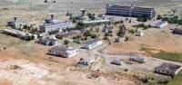
Site 44, IP-2 (Testing point) (formerly IP-1B), 25 OIS, The second measuring point of the test site is located at an altitude of 109 meters above sea level, located in the eastern part of the Baikonur Cosmodrome. On May 15, 1960, a new stationary measuring point IP-1B was formed at the Baikonur training ground.
It was formed on the basis of IP-1. IP-1B was located on site 43, 1 kilometer from MIK-42, 800 meters from the launch site 41 for R-16 and 8 kilometers from launch site 31 (R-7A), and was intended to provide pre-launch preparation of products at these sites and work at OUT.
Later, after the KTS cinema theodolite was transferred from optical IP-2 to IP-1 B, the latter was renamed IP-2. IP-1 B was located on a small hill, adjacent to the warehouses and residential camp of site 43. IP-1 B had two brick one-story technical buildings (one VTI and SEV, the second telemetry), a reinforced concrete pylon for the new high-efficiency antenna TNA-100 (developed OKB-MEI) and two aggregate stations for gasoline units and diesel engines.
A kilometer ahead and to the left of IP-1B, the Orion mobile phase-metric single-point VTI system was deployed, designed to replace the Irtyshi. The BRS-1 station (fast recording station) was developed by the team of Ivan Ivanovich Utkin, who was initially part of NII-88. and then separated into an independent research institute of measuring technology, research institute of IT.
Before this, the team worked on sensors and autonomous recorders. BRS was the first radio system developed by the team. Therefore, the station had many shortcomings; it was capricious, unstable, and difficult to operate.
It consumed a lot of electricity; numerous DC amplifiers “floated” and required constant adjustment. There were even errors such as incorrect calculation of the wire cross-section and reduced lamp voltage. It should be said that the construction of this system was a difficult task and E.S. Gubenko, when he was offered to develop such a station, refused to do so. BRS-1 had 16 functional channels, with a sampling frequency of each 8 kHz.
General information content 160 kHz, useful 128 kHz, accuracy 6%. The duration of the measuring pulses is 3.1 μs, the duration of the frame pulse is 9.3 μs. AIM-HMI modulation. For the first time in the country, a multi-track telemetric tape recorder was created, which was also used at the Tral-K station.
The standard IS-1788 double-helix antenna with a mesh rectangular reflector with rounded corners had an effective surface in the middle of the meter range of more than 3 square meters. The sensitivity of the receiver is 10 microvolts, the power of the onboard transmitter is 15 W, the operating range is 800 kilometers. Information was recorded on a wide 32 mm magnetic tape using a multi-track tape recorder.
Information processing was carried out using the “Spectrum Analyzer” equipment, which was attached to each station and turned out to be strictly individual, which caused great complaints from the processors after the transfer of this equipment to the processing department at sites 10.
The TNA-100 antenna developed by OKB MPEI (installed in early 1961) had 4 spirals 6 m long with separate mesh square reflectors. It was guided by the drive of an anti-aircraft ship installation with a manual local and electric remote drive in angle and speed from a small remote control installed on the table at a speed of up to 6 degrees / s.
The radiation pattern width is more than 20°, the effective surface in the lower part of the meter range is 80 - 100 square meters. This antenna met all test requirements and provided improved reception in areas exposed to plasma formations, both at OUT and NAPUT.
The Tral-K stations were installed on IP-1B and were tested in 1961 - 1962. in mobile version: 2 hardware vehicles and the TNA-27 antenna on a four-wheel trailer from under a mobile anti-aircraft gun. The surface wave antenna, 6 meters long, had 5 guide disks, two mutually orthogonal linear polarization loop vibrators and a square mesh reflector.
The Tral-K stations provided the ability to automatically process magnetic tape on a specialized computer (SEVM) “Start” developed by I.I. Utkin’s team. The Tral-K station was designed to work with the new on-board devices Tral-K, Tral-Sh-28, which had expanded capabilities for transmitting signal parameters and parameters of the second stage of switching (up to 11,250 polls/sec useful information content).
The station recorded information on a 32 mm wide magnetic tape. This film was delivered to site 10 for processing on the Start computer, which was initially located in the basement of the test site headquarters building.
Before the construction of the CC building, the Spectrum Analyzer equipment was located there. The Tral-K mobile stations were mock-ups. Since 1963, fixed stations have been supplied. The "Kama-E" station was a further development of the "Binoculars", "Binoculars-D" station with an improved radio link and a system for acquiring and automatically tracking a target with an antenna (diameter 3 meters), with an improved system for storing, averaging and entering information into communication lines using ICM "Temp" for the computer center.
The first mobile station "Kama" was deployed at IP-1. The first stationary station “Kama” was deployed in June 1960 at IP-1 B, at the remaining IPs in the “Tundra” region - until April 1961. The first "Temp" was also deployed on IP-1B on December 7, 1960, on other IPs until December 1961.
The Orion system, a single-point phase-metric system, was late for the start of testing, there was a lot of fuss with it, but no significant positive results were obtained. In 1964, IP-2 successfully tested a new system for measuring rapidly changing parameters BRS-4, developed by NII-88 (Chief Designer I.I. Utkin).
The BRS-4 system, designed for measuring rapidly changing parameters, had twice the information content of the BRS-2. General information content - 320000, useful - 304000 measurements per second. Work on launching from the launch site 31, 8 kilometers away (a hill on the horizon on the right).
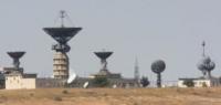
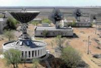
The rocket launched. The MA-9MKTM-4 complex with the B-529 “Romashka” antenna (the second antenna on the right in the building) and the MA-9MKTM-1 station, located in the distant technical building in the center of the picture, with the “Izumrud” antenna (the right antenna on pylon in the distance).
In the photo from left to right: the one-story technical building “Orbita” with the MA-9MKTM-1 stations and the Kedr and Delta antennas in front of the building. Behind it is the TNA-103 antenna and a one-story technical building No. 2 with Tral-K2N stations.
Behind it is the diesel and optics building with two domes of the KST-80 and KTS towers. To the right is a two-story building for a complex of PRA-M stations with wiring according to the 11K77 Zenit project. In the foreground in the center is the TNA-57U antenna.
Behind it in the background is a one-story building PRA-M and MA-9MKTM-1. To the right are two one-story buildings MA-9MKTM-4. On one, the antenna has not yet been mounted. The pylons of K-529A and Emerald are turning white. 1987.
Geographic coordinates of Measuring point at site 44: N45°58'23.71" E63°38'47.96"
Authority:
V.V. Poroshkov. http://www.kik-sssr.ru
Photos by:
Alexander Petrov and V.V. Poroshkov.